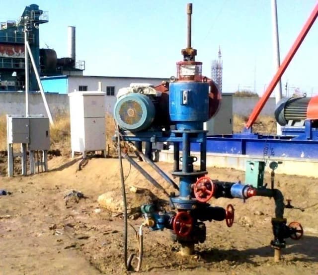
GBF
Bevel gear drive
Lower-power configurations.
ARTIFICIAL LIFT / PROGRESSING CAVITY PUMPS
Connect the downhole pump, elastomer and surface drive around the fluid you produce and the conditions you operate in.
Surface-driven PCP · Permanent magnet drives · ESPCP
FROM SURFACE POWER TO DOWNHOLE PRODUCTION
Operating speed and control
Torque, axial load and braking
Mechanical power transmission
Fluid displacement and lift
DOWNHOLE PUMP RANGE
Find a starting point for engineering review. Final selection depends on your actual well conditions.
Flow is normalized to 100 rpm. Water-column head is not setting depth. Select up to three models. GLB521 is listed as 520 mL/rev in the source; confirmation is required.
| Select | Model | Displacement mL/rev | Reference flow m³/day at 100 rpm | Stages | Water-column head m | PDF page |
|---|---|---|---|---|---|---|
| GLB28-18 | 28 | 4.0 | 18 | 800 | 8 | |
| GLB28-27 | 28 | 4.0 | 27 | 1200 | 8 | |
| GLB28-40 | 28 | 4.0 | 40 | 1800 | 8 | |
| GLB28-55 | 28 | 4.0 | 55 | 2500 | 8 | |
| GLB40-21 | 40 | 5.8 | 21 | 950 | 8 | |
| GLB40-27 | 40 | 5.8 | 27 | 1200 | 8 | |
| GLB40-45 | 40 | 5.8 | 45 | 2000 | 8 | |
| GLB75-21 | 75 | 10.8 | 21 | 950 | 8 | |
| GLB75-27 | 75 | 10.8 | 27 | 1200 | 8 | |
| GLB75-40 | 75 | 10.8 | 40 | 1800 | 8 | |
| GLB75-50 | 75 | 10.8 | 50 | 2250 | 8 | |
| GLB105-21 | 105 | 15.1 | 21 | 950 | 8 | |
| GLB105-27 | 105 | 15.1 | 27 | 1200 | 8 | |
| GLB105-40 | 105 | 15.1 | 40 | 1800 | 8 | |
| GLB105-50 | 105 | 15.1 | 50 | 2250 | 8 | |
| GLB120-21 | 120 | 17.3 | 21 | 950 | 8 | |
| GLB120-27 | 120 | 17.3 | 27 | 1200 | 8 | |
| GLB120-36 | 120 | 17.3 | 36 | 1600 | 8 | |
| GLB120-40 | 120 | 17.3 | 40 | 1800 | 8 | |
| GLB170-21 | 170 | 24.5 | 21 | 950 | 8 | |
| GLB170-27 | 170 | 24.5 | 27 | 1200 | 8 | |
| GLB170-36 | 170 | 24.5 | 36 | 1600 | 8 | |
| GLB170-40 | 170 | 24.5 | 40 | 1800 | 8 | |
| GLB190-21 | 190 | 27.4 | 21 | 950 | 8 | |
| GLB190-27 | 190 | 27.4 | 27 | 1200 | 8 | |
| GLB190-33 | 190 | 27.4 | 33 | 1500 | 8 | |
| GLB190-40 | 190 | 27.4 | 40 | 1800 | 8 | |
| GLB230-21 | 230 | 33.1 | 21 | 950 | 9 | |
| GLB230-27 | 230 | 33.1 | 27 | 1200 | 9 | |
| GLB230-33 | 230 | 33.1 | 33 | 1500 | 9 | |
| GLB230-40 | 230 | 33.1 | 40 | 1800 | 9 | |
| GLB300-21 | 300 | 43.2 | 21 | 950 | 9 | |
| GLB300-27 | 300 | 43.2 | 27 | 1200 | 9 | |
| GLB300-33 | 300 | 43.2 | 33 | 1500 | 9 | |
| GLB410-21 | 410 | 59.0 | 21 | 950 | 9 | |
| GLB410-27 | 410 | 59.0 | 27 | 1200 | 9 | |
| GLB410-33 | 410 | 59.0 | 33 | 1500 | 9 | |
| GLB410-40 | 410 | 59.0 | 40 | 1800 | 9 | |
| GLB521-21 | 520 | 75.0 | 21 | 950 | 9 | |
| GLB521-27 | 520 | 75.0 | 27 | 1200 | 9 | |
| GLB521-33 | 520 | 75.0 | 33 | 1500 | 9 | |
| GLB521-40 | 520 | 75.0 | 40 | 1800 | 9 | |
| GLB625-21 | 625 | 90.0 | 21 | 950 | 9 | |
| GLB625-27 | 625 | 90.0 | 27 | 1200 | 9 | |
| GLB625-33 | 625 | 90.0 | 33 | 1500 | 9 | |
| GLB700-21 | 700 | 100.8 | 21 | 950 | 9 | |
| GLB700-27 | 700 | 100.8 | 27 | 1200 | 9 | |
| GLB700-33 | 700 | 100.8 | 33 | 1500 | 9 | |
| GLB800-14 | 800 | 115.2 | 14 | 650 | 9 | |
| GLB800-20 | 800 | 115.2 | 20 | 900 | 9 | |
| GLB800-27 | 800 | 115.2 | 27 | 1200 | 9 | |
| GLB1000-14 | 1000 | 144.0 | 14 | 650 | 9 | |
| GLB1000-20 | 1000 | 144.0 | 20 | 900 | 9 | |
| GLB1000-27 | 1000 | 144.0 | 27 | 1200 | 9 | |
| GLB1100-14 | 1100 | 158.4 | 14 | 650 | 9 | |
| GLB1100-18 | 1100 | 158.4 | 18 | 800 | 9 | |
| GLB1100-21 | 1100 | 158.4 | 21 | 950 | 9 | |
| GLB1400-14 | 1400 | 201.6 | 14 | 650 | 9 | |
| GLB1400-18 | 1400 | 201.6 | 18 | 800 | 9 |
THE FLUID DETERMINES THE MATERIAL
Share temperature, fluid chemistry, aromatics, gas and solids data to assess swelling, wear and mechanical properties.
| Material | Working temperature | Maximum temperature | Application considerations |
|---|---|---|---|
| GY-1 | 80 °C | 90 °C | Water-cut oil with small solid content; CO₂ exposure needs assessment. |
| GY-2 | 100 °C | 120 °C | Light oil with aromatic compounds; wear resistance is an evaluation factor. |
| GY-3 | 80 °C | 90 °C | High solids, sand and water-cut service; particle conditions must be supplied. |
| GY-4 | 120 °C | 130 °C | Aromatic compounds, CO₂, water and small amounts of H₂S; concentration limits need review. |
| GY-5 | 150 °C | 170 °C | Aromatic compounds and acid-gas exposure; swelling and mechanical properties need review. |
| GY-P | 80 °C | 90 °C | Coal-seam water; evaluate actual water chemistry and wear conditions. |
| GY-A | 120 °C | 130 °C | High-temperature and chemical exposure; mechanical-property trade-offs need review. |
| GY-F | 180 °C | 200 °C | High-temperature chemical service; these are material figures, not system ratings. |
Maximum temperature is not a continuous-duty guarantee. Chemical concentration limits and complete system compatibility require engineering confirmation.
MATCH THE PUMP TO THE DRIVE
GBF
Lower-power configurations.
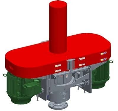
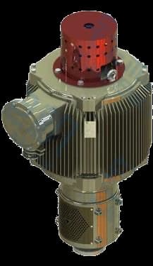
VED
Centrifugal braking; high-torque configurations.
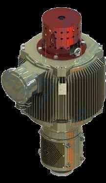
PMM
Direct motor drive with configuration-specific braking.
| Model | Speed / rated speed rpm | Torque N·m | Power kW | Axial load | PDF page |
|---|---|---|---|---|---|
| GBF6 | 50–260 | 1500 | 7.5–22 | 60 kN | 12 |
| GBF2 | 120–500 | 2000 | 11–37 | 100 kN | 12 |
| GBF5Y | 60–320 | 2500 | 11–37 | 150 kN | 12 |
| GBF5D | 50–300 | 3000 | 22–55 | 200 kN | 12 |
| VED2000 | To be confirmed | 2000 | To be confirmed | 12 t | 13 |
| VED2700 | To be confirmed | 2700 | To be confirmed | 19 / 30 t | 13 |
| VED2700D | To be confirmed | 2700 | To be confirmed | 19 / 30 t | 13 |
| VED5000D | To be confirmed | 5000 | To be confirmed | 30 t | 13 |
| PMM10-450 | 450 | 1000 | 47.1 | Confirm configuration | 14 |
| PMM12-450 | 450 | 1200 | 56.5 | Confirm configuration | 14 |
| PMM16-450 | 450 | 1600 | 75.4 | Confirm configuration | 14 |
| PMM20-450 | 450 | 2000 | 94.2 | Confirm configuration | 14 |
| PMM24-450 | 450 | 2400 | 113.1 | Confirm configuration | 14 |
| PMM27-450 | 450 | 2700 | 127.2 | Confirm configuration | 14 |
| PMM35-450 | 450 | 3500 | 164.9 | Confirm configuration | 14 |
| PMM40-450 | 450 | 4000 | 188.5 | Confirm configuration | 14 |
| PMM10-300 | 300 | 1000 | 31.4 | Confirm configuration | 14 |
| PMM12-300 | 300 | 1200 | 37.7 | Confirm configuration | 14 |
| PMM16-300 | 300 | 1600 | 50.3 | Confirm configuration | 14 |
| PMM20-300 | 300 | 2000 | 62.8 | Confirm configuration | 14 |
| PMM24-300 | 300 | 2400 | 75.4 | Confirm configuration | 14 |
| PMM27-300 | 300 | 2700 | 84.8 | Confirm configuration | 14 |
| PMM35-300 | 300 | 3500 | 109.9 | Confirm configuration | 14 |
START WITH OPERATING CONDITIONS
Review particle size, concentration and abrasion with PCP geometry and GY-3 material candidates.
Discuss this application ↗Assess actual water chemistry and wear exposure with the GY-P material option.
Discuss this application ↗Review working temperature, aromatics, CO₂ and H₂S before selecting an elastomer.
Discuss this application ↗ESPCP connects a downhole pump, permanent magnet motor, protector, cable and surface controls. The brochure system table lists 120 °C; motor figures do not extend that rating.
Discuss this application ↗Brochure PDF pages 10–17. These pathways support engineering review and do not constitute automatic selection or performance guarantees.
ENGINEERING RESOURCES
Target flow and units, fluid temperature, viscosity and measurement temperature, sand/water/gas data, well geometry, setting depth, available power and existing equipment. Unknown values can be supplied later.
No. Actual performance depends on speed, fluid properties, slip, loading and system constraints. Reference flow and water-column head need engineering assessment.